
BWM ReferenceWiring
ELECHOUSE ST25R3916B: SPI wiring
Signal connections for the seven-pin module in the V0.3 Draft datasheet.
Applies to: V0.3 Draft, 2026-07-18; not the Mini module or the chip package. Confirm connector orientation against the original board drawing.
When to use it
Using this exact ELECHOUSE module in its documented default SPI mode.
Why it works this way
IRQ is additional to the four SPI signals.
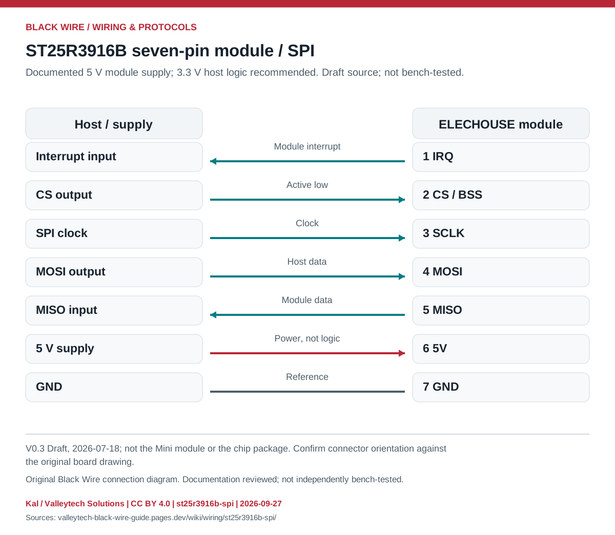
Connection reference
| Contact | SPI signal | Host connection |
|---|---|---|
| 1 | IRQ | Interrupt input |
| 2 | CS / BSS | Chip-select output |
| 3 | SCLK | SPI clock |
| 4 | MOSI | MOSI |
| 5 | MISO | MISO |
| 6 | 5V | Module supply |
| 7 | GND | Ground |
Make the connection
- Match the seven-pin board and default SPI configuration.
- Use the module's supported library and its documented startup sequence.
Check before powering
- The 5V label does not make the signals 5 V tolerant.
Matching module references
Sources & review
Source documents inspected; independent electrical and bench review pending. Reviewed 2026-09-27.
- ELECHOUSE ST25R3916B module, V0.3 Draft
Page 4: seven-pin connector, power and SPI/I2C mode selection · checked 2026-09-27 - Analog Devices: Introduction to SPI Interface
Interface, signal direction and CPOL/CPHA table · checked 2026-09-27
Original writing and diagram by Kal / Valleytech Solutions, CC BY 4.0. Manufacturer artwork and documentation retain their own rights. CC BY 4.0
Diagram fingerprint
cfdf9798defa8349fd3273fe605d6596ba57d4a2bbf48b11f1c6eb9828031bbd