
BWM ReferenceWiring
SWD: connect a Cortex debug probe
Map the essential debug signals without confusing voltage sense with a power output.
Applies to: Five signal connections using the cited Cortex 10-pin numbering. It is not a complete 10-pin map or a map for every ST-Link clone.
When to use it
Programming or debugging a target that explicitly supports Arm Serial Wire Debug.
Why it works this way
SWD uses a bidirectional data signal and a clock, with target voltage reference and ground.
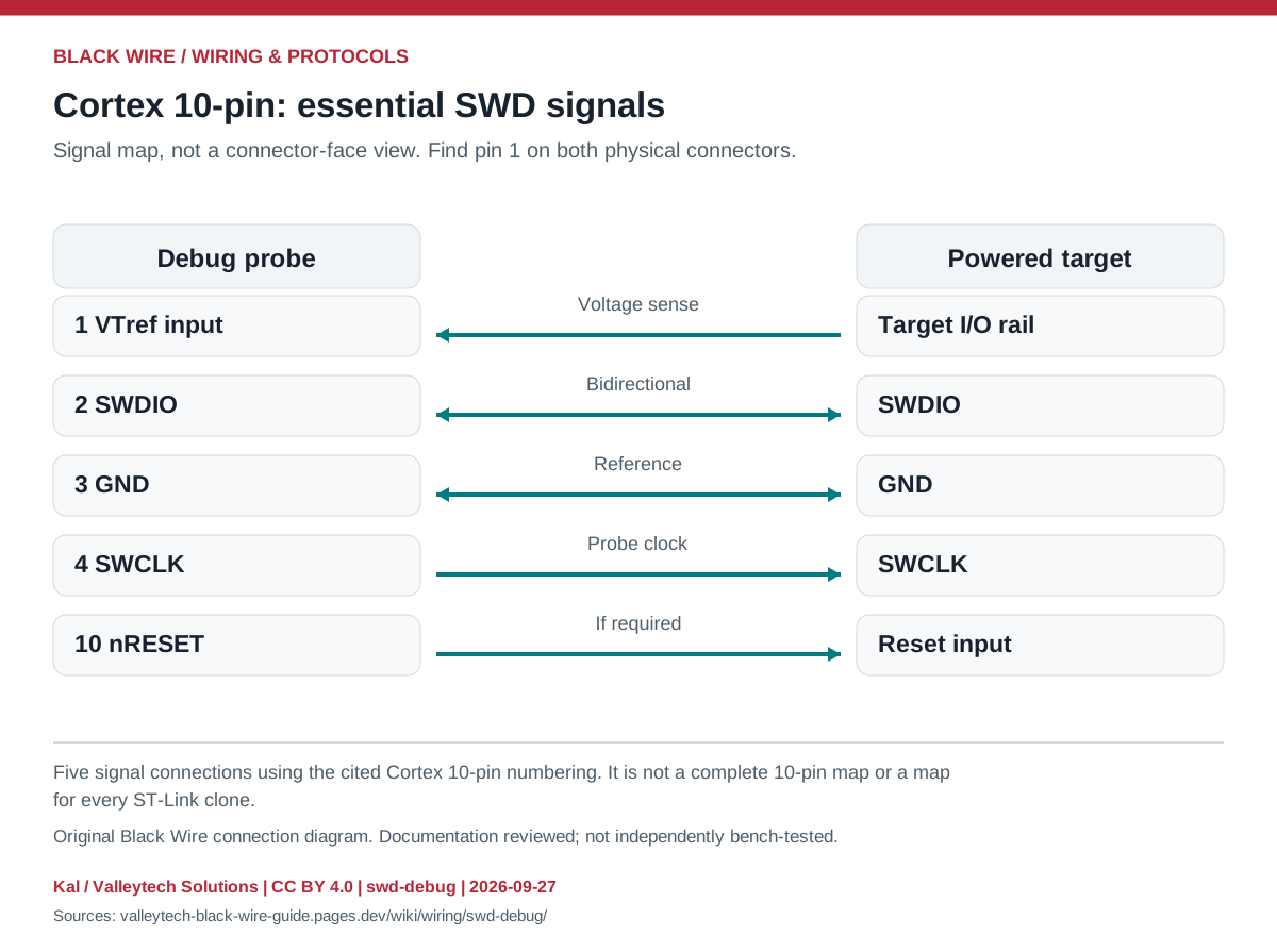
Connection reference
| Cortex contact | Signal | Role |
|---|---|---|
| 1 | VTref | Sense target I/O voltage |
| 2 | SWDIO | Bidirectional data |
| 3 | GND | Reference |
| 4 | SWCLK | Probe output |
| 10 | nRESET | Target reset, if used |
Make the connection
- Use the actual probe and board connector drawings and match pin 1.
- Power the target as documented and connect its I/O rail to VTref.
- Select SWD and start with a conservative debug clock.
Check before powering
- VTref normally senses power; it is not permission to power the target from the probe.
- Optional SWO and unused contacts depend on the target. SWD and JTAG are different modes.
Sources & review
Source documents inspected; independent electrical and bench review pending. Reviewed 2026-09-27.
- Microchip: Cortex Debug Connector (10-pin)
Connector drawing and SWD signal table · checked 2026-09-27 - Arm Keil: Application Note 321, version 1.1
Page 18: five SWD connections and Cortex 10-pin numbers · checked 2026-09-27
Original writing and diagram by Kal / Valleytech Solutions, CC BY 4.0. Manufacturer artwork and documentation retain their own rights. CC BY 4.0
Diagram fingerprint
41cd2f2fadce0165708e062a01c37af3551378cd28a2b85a601f79e9e5c5f444