
BWM ReferenceWiring
SPI: clock, data direction and chip select
Connect a host to a four-wire SPI peripheral without crossing the data roles.
Applies to: Conventional four-wire, active-low-CS SPI. Three-wire, daisy-chain and device-specific interfaces need their own diagrams.
When to use it
Using supported displays, memory, ADCs or radio/NFC frontends.
Why it works this way
A shared clock times the transfer, and chip select identifies the active peripheral.
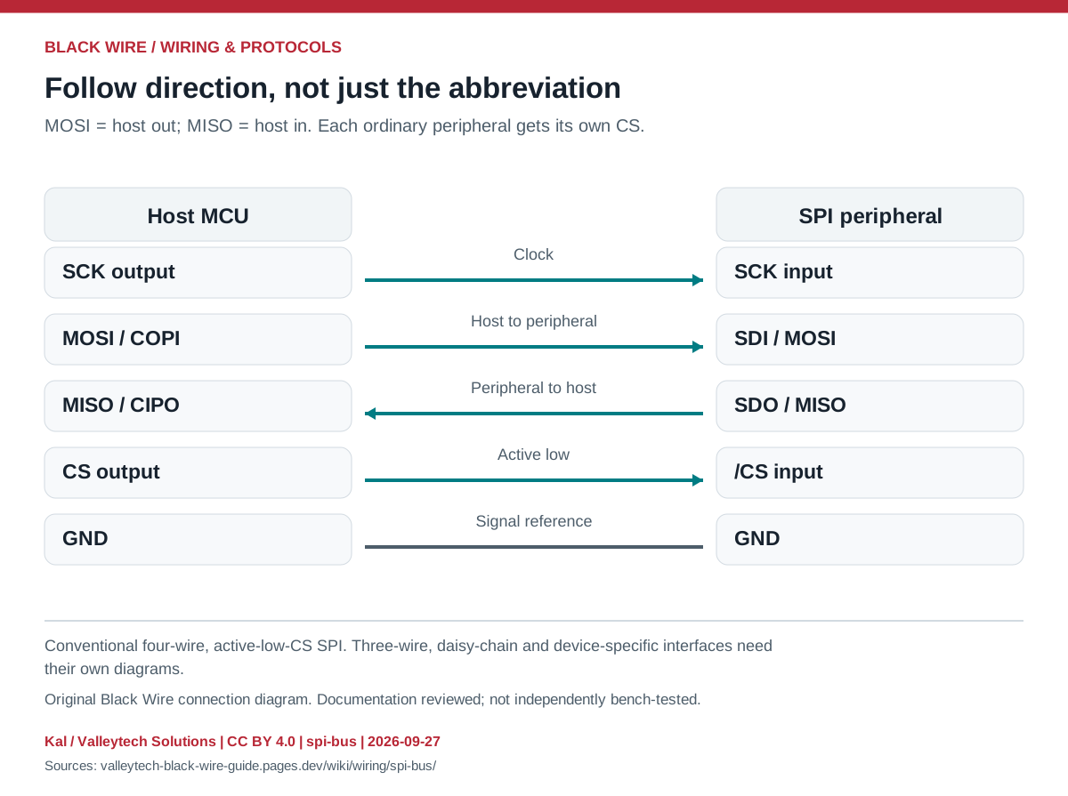
Connection reference
| Mode | CPOL | CPHA |
|---|---|---|
| 0 | 0 | 0 |
| 1 | 0 | 1 |
| 2 | 1 | 0 |
| 3 | 1 | 1 |
Make the connection
- Match I/O levels, SPI mode, bit order and maximum clock to the peripheral datasheet.
- Check that shared MISO devices release the line when deselected.
- Start with short wires and a conservative clock.
Check before powering
- SDI/SDO labels are local to the device. Read each signal direction.
- Supply wiring and optional IRQ/reset signals are additional to the four SPI signals.
Sources & review
Source documents inspected; independent electrical and bench review pending. Reviewed 2026-09-27.
- Analog Devices: Introduction to SPI Interface
Interface, signal direction and CPOL/CPHA table · checked 2026-09-27
Original writing and diagram by Kal / Valleytech Solutions, CC BY 4.0. Manufacturer artwork and documentation retain their own rights. CC BY 4.0
Diagram fingerprint
5232f621f0b93104e041b3032a1f339bf244e7dc721a7cf8b7b80a885e3daa02